Active HVAC Systems
Heating, Ventilation and Air Conditioning (HVAC) systems help keep building occupants comfortable. HVAC systems are usually designed by mechanical engineers and typically account for 30% or more of a buildings total energy use. An effective HVAC strategy is essential for a Net Zero Energy Building.
HVAC basics
Traditional HVAC systems heat or cool air that is then forced throughout the building. To improve efficiency, look for equipment with a high coefficient of performance or energy efficiency ratio. Also, maximize the whole system with integrative design. For example, heat exchanging systems can condition incoming air with energy from exhaust air. HVAC equipment that doesn’t use forced air, like chilled beams and radiant panels, can also be very efficient.
HVAC Equipment

Mechanical heating and cooling uses electricity or burning fuel to achieve thermal comfort in buildings. They are also called HVAC (Heating, Ventilation, and Air Conditioning) systems. They include air conditioners, boilers, chillers, heat pumps, dehumidifiers and humidifiers, radiant systems, and other types of equipment.
Nearly all modern buildings use mechanical heating and cooling. It comprises roughly a third of commercial building energy use. While passive heating and cooling systems can do the most to reduce building energy use, well-designed mechanical systems are necessary for peak performance. Moreover, HVAC systems and passive systems need to work well together to achieve peak performance.

Building with HVAC systems on its roof
When heating a building, heat can either be generated or pumped from outside to inside. When cooling a building, heat can only be pumped from inside to outside, it cannot be annihilated.
To be more accurate, heat is not generated, but converted from chemical energy to heat by burning fuel, or converted from electrical energy to heat through resistive heating. These conversions are easy, but converting heat to other forms of energy requires a large temperature difference that is generally not found in building systems. Hence all cooling in buildings is simply moving heat from one place to another.
Heat Generation Systems
Furnaces and Boilers
Furnaces burn fuel to create heat. While they can directly heat air, they most commonly heat water circulating in a closed loop, which heats the air. Such systems are called boilers.

A residential heating oil boiler
Furnaces and boilers can burn natural gas, “heating oil” (a grade of diesel fuel), wood, or any other combustible fuel. Natural gas provides the least harmful emissions among fossil fuels, but some biofuels can have even less.
To keep indoor air quality high, furnaces and boilers must exhaust the fumes of their burning fuel to the outside air; some of the heat generated by combustion is lost with the fumes. The efficiency of furnaces and boilers is measured in annual fuel utilization efficiency, AFUE. The higher the AFUE, the more efficient the system. For example, a 90% AFUE means that for every Btu of gas burned, the system provides 0.9 Btu of heat to the building and 10% escapes. Old inefficient systems may have as low as 70% AFUE, while modern efficient systems may have up to 97% AFUE.
Electric Resistance Heaters
Electric resistance heaters are simply large resistors that heat up as current is sent through. Baseboard heaters use electricity to heat up air directly; electric boilers heat up water that either heats air or heats a radiant system.

Electric baseboard heater
Electric heaters have no fumes to expel. As such, the core system is 100% efficient at energy conversion. Any AFUE lower than 100% is due to losses in the housing if the unit is located outside.
For Net Zero Energy buildings, resistance heaters can be powered by solar photovoltaics, with no need for fossil fuels. However, if they are powered from grid electricity that primarily comes from burning fossil fuels, they may actually cause more fuel burning and emissions than an on-site fuel-burning boiler, due to the difference between site energy and source energy.
Solar Thermal
Solar thermal water heaters can also be used to generate heat for HVAC. They are more effective for climates that are cold but sunny, and less effective for climates that are cloudy or dark when they are cold. Because sunlight is free, their efficiency does not drive performance as much as the size and cost of the system. They are generally less expensive than solar photovoltaics powering electric heaters.
Heat Moving Systems
Heat pumps move heat from one place to another. Because heat pumps are not generating heat but just moving heat from one place to another, it can seem like they are over 100% efficient. A heat pump in heating mode can move 2 to 5 times as much heat energy as it consumes in electricity; a heat pump in cooling mode can move 3 to 12 times as much heat energy as it uses in electricity.
Some can pump heat both out of and into a building – and thus provide both heating and cooling. An air conditioner (or “chiller” for large-scale systems) is a kind of heat pump that only pumps heat out of a building, but does it slightly more efficiently than heat pumps that can pump both ways.

Heat pumps can move several units of heat energy per unit of electricity
HVAC System Size and Efficiency
The amount of heating or cooling a specific HVAC system can deliver depends on its size. Since buildings cannot conveniently swap out one system for another on the fly, engineers must size equipment for worst-case scenarios.
The trouble with oversizing HVAC systems is that they are less efficient than systems that are sized appropriately. Often systems are radically oversized, “just in case”. Such systems can be up to 35% less efficient than a properly-sized system. In retrofits, such oversizing can eliminate the improvement from replacing an old system with a new efficient system.

Doubling the size of a particular class of air conditioner cuts its efficiency 25%. (From AdvancedEnergy.org.)
An HVAC system should be sized for a project only after all other features of the building have been optimized. Design the building form, mass, and openings to take full advantage of passive heating, cooling, ventilation, and daylighting opportunities. Ideally, many or most days of the year the building can achieve thermal comfort entirely passively, so that active heating and cooling are merely a supplement or backup.
Heat Pumps
Heat pumps move heat from one place to another. Some can pump heat both out of and into a building, for cooling or heating. Air conditioners(or “chillers” for large-scale systems) are a kind of heat pump that can only pump heat out of a building, but can do it slightly more efficiently than bi-directional heat pumps.

Small-scale heat pumps.
Heat pumps are important for efficient HVAC systems because moving heat can use less energy than generating heat. Heat generators can never be more than 100% efficient because the energy they use is directly creating heat, but heat pumps effectively can because they just move heat from one place to another. However, based on the operating environment, sometimes boilers are more effective. This is the case particularly in cold outdoor temperatures (below 5°C or 40°F).
To think about moving heat rather than generating it, imagine a tanker truck driving fuel from one place to another–the truck may be hauling thousands of liters of fuel as cargo, but truck’s own gas tank only holds a few dozen gallons, because that’s all the fuel it needs to burn to carry the load to its destination. In the same way, heat pump move heat energy as cargo, using a bit of electric energy to do so.
Measuring Efficiency
There are many ways to measure the effectiveness of a heat pump:
COP (coefficient of performance) is the simplest measurement. It measures the amount of heat energy moved (in watts), divided by the electric energy used to move it (also in watts), at a given outdoor temperature. Higher COP values indicate a more efficient system. An electric resistance heater generating heat at 100% efficiency will have COP = 1, while a heat pump in heating mode ranges from a COP of 2 to 5, and a heat pump in cooling mode ranges from 3 to 12.
EER (energy efficiency ratio) is similar to COP, but for only for cooling. It measures how efficiently a cooling system operates. EER is most commonly applied to window units and smaller standalone air conditioners and heat pumps. The EER is the ratio of Btu/hr of cooling divided by the watts of electricity used at an outside temperature of 95°F (35°C). Room air conditioners should have an EER of at least 9.0 for mild climates and over 10.0 for hot climates.
SEER (seasonal energy efficiency ratio) measures how efficiently a smaller residential air conditioner or heat pump operates over an entire cooling season, as opposed to a single outdoor temperature. As with EER, a higher SEER reflects a more efficient cooling system. SEER is the ratio of the total amount of cooling Btu’s the system provides over the entire season divided by the total number of watt-hours it consumes.
HSPF (heating seasonal performance factor) measures how efficiently heat pumps operate in heating mode over an entire heating season. It is like SEER but for heating. The higher the HSPF, the more efficient the system. HSPF is calculated by dividing the total number of Btu’s of heat delivered over the heating season by the total number of watt-hours of electricity required to deliver that heat.
kW/ton measures the energy input in kW over the tons of cooling provided. Unlike other metrics, the lower the ratio, the more efficient the chiller. This metric is most often used to determine efficiency of large-scale chillers.
| Operating Mode | Design Rated Conditions | Seasonal Average Conditions |
| Cooling |
COP
EER
kW/ton
|
COP
SEER
|
| Heating | COP |
COP
HSPF
|
Table of different heat pump efficiency measures(from Engineering Toolbox)
How Heat Pumps Work
Heat pumps work the same way a refrigerator does–by having a gas condense to liquid and then expand again, within a loop of rigid tubing that extends from the hot side to the cold side. This moves heat because of the ideal gas law, which says that as pressure increases, temperature increases; as pressure decreases, temperature decreases.
Thus, when the gas expands on one side of the tubing loop, its temperature decreases and it pulls heat into it from the surroundings. This becomes the cold side of the loop. The gas is then pumped to the other side of the loop and pressurized by an electric compressor until it becomes a liquid. This rise in pressure raises the temperature, so the liquid pushes heat out to its surroundings. This becomes the hot side of the loop. After dumping its heat outside, the fluid goes through a valve to allow it to expand to a gas again on the other side of the loop, starting the cycle over.

Diagram of a heat pump cycle, in cooling mode

Diagram of a heat pump cycle, in heating mode
In theory, one side of the tubing loop is indoors while the other is outdoors, but in reality this is usually costly and difficult to plumb, because the loop’s “working fluid” is a volatile gas. These gases should not be allowed to escape, because they usually have adverse environmental impacts such as climate change and ozone depletion. Thus, usually both sides of the loop are in the heat pump unit, and the “indoor” side contacts indoor air brought to it by a duct, or contacts a separate loop of water that circulates to ducts or radiant systems.
Heat Pump Sources
Air
Air-Source Heat Pumps dump their exhaust heat (or cooling) to the outside air. They are the vast majority of heat pump systems. For large chillers, the unit dumping heat into the outside air is usually called the cooling tower.

Cooling tower for a moderate-sized commercial HVAC system
Air source heat pumps are popular because they are the least expensive and easiest to install, as they do not require digging into the earth or extensive piping systems. However, they lose efficiency when heating buildings on cold days (below 5°C / 40°F).
Earth
Ground Source Heat Pumps(“GSHP”, or “geothermal” heat pumps) dump their exhaust heat (or cooling) to the ground instead of the air. Because the ground stays at a relatively stable temperature all year, they can be much more efficient than air source heat pumps on very hot or cold days.

Ground temperature stays relatively constant while air temperature varies wildly
All ground source heat pumps work by pumping a heat-conductive fluid (usually water or propylene glycol) through loops of pipe in the ground. “Horizontal” systems install the pipes by digging a shallow (1-3 m / 3-8 ft. deep) but wide trench in the ground, laying coils of pipe, and covering it back up with earth. “Vertical” systems dig deep but narrow wells (usually 30-150 m / 100-500 ft. deep). Horizontal systems are less expensive to install, but take more land area and do not have as stable ground temperature as deeper wells.


Installing horizontal (top) and vertical (bottom) plumbing of ground source heat pumps
The disadvantage of ground source heat pumps is that the digging and plumbing required to install them is expensive. A medium-sized commercial building might require hundreds of wells to be dug and plumbed for a GSHP system.
Water
Some ground source heat pumps actually use rivers, ponds, or other bodies of water for their heat sink. Closed-loop systems use effectively the same hardware and work the same way as ground source heat pumps.
However, it is also possible to install “open-loop” systems, whose pipes are literally open to the stream. These pull water in one end, bring it to the heat pump where heat is dumped into it or pulled from it, and pump the newly heated or cooled water back into the river downstream. These can also use groundwater from separate wells, pumping from one into another.

Installing a water-source heat pump by sinking coils of pipe
Water-source heat pumps have the performance advantages of ground-source heat pumps, and can even perform better due to water’s high conductivity and high heat capacity. They can also be less expensive to install, depending on the local conditions. However, they are of course limited to sites where a body of water (or hidden groundwater) is convenient, and where the extra heating or cooling will not disrupt the water’s ecosystem.
Absorption Chillers
Absorption chillers are heat pumps in which the compression and evaporation of the working fluid is not controlled by an electrically-powered pump, but instead driven by an external heat source.
In absorption chillers, the gaseous working fluid is absorbed by a second chemical, such as ammonia, which brings it back to a liquid state. The second chemical is then driven off by heat and the working fluid is returned to the cooling loop as a liquid.

An absorption chiller’s dual cycle. (Click to enlarge.)
Absorption chillers are significantly less efficient than electrically-pumped units (with COPs around .7 to 1.2), but they can operate off of waste heat. In these cases, their efficiency is unimportant, because the energy source is free and does not cause any environmental impacts to use.
This is the same technology used by gas-powered refrigerators
Radiant Heating and Cooling
Radiant heating and radiant cooling systems are different from typical HVAC systems because they heat or cool surfaces rather than air. The warm or cool surfaces then radiate heat to occupants. The surfaces also conduct heat to people that touch them, and warm or cool the air by convection as well.
Radiant systems can save large amounts of energy while also providing better comfort, depending on the building and the climate. Traditional systems use standalone radiators, while modern systems are often built into floors or ceilings.
Spaces with large air volumes and large amounts of unavoidable infiltration, such as loading docks and warehouses, are especially good building programs for radiant floor heating because heating the air would be inefficient. Radiant floors are also an excellent choice for residential spaces where people may walk barefoot.
Even in more typical applications, radiant systems are more efficient than forced air heating or cooling because there are no duct losses. Also, in heating applications, heat is delivered low in the room where occupants are, rather than at the ceiling from overhead ducts.

Heating a person with a radiant floor vs. forced air system
Radiant systems are not for all situations. They are not useful for humidity control; in fact, radiant cooling is best for dry climates because it can cause condensation in humid air. Radiant surfaces should also not be covered with carpet, acoustic panels, or other materials that would insulate them and hamper their effectiveness. Finally, they should ideally have large surface areas to provide large amounts of evenly-distributed heating or cooling.
Mean Radiant Temperature
Successful radiant heating or cooling is measured by the mean radiant temperature (“MRT”) of the space, and the energy used to keep people comfortable. Mean radiant temperature is simply a weighted average of the temperatures of all surfaces in a room (including people and equipment), with each temperature weighted by the size of the area at that temperature.

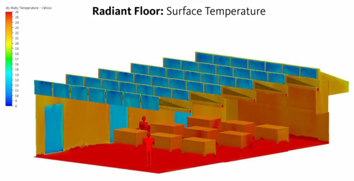
Temperatures of interior surfaces color-coded
The image above shows surface temperatures throughout the interior of a room. People appear as red due to their warmth, and the floor is warm due to a radiant heat system. Walls and furniture are orange, because they are at the same temperature as the air. Windows appear blue because they are losing heat by radiating it to the outside.
Mean radiant temperature is the single most important parameter in human thermal comfort. It has the strongest influence on comfort indexes such as Predicted Mean Vote (“PMV”) or Physiological Equivalent Temperature (“PET”). Air temperatures matter less. Thus heating and cooling systems that address radiant temperatures directly can be more efficient than those that heat or cool air.


Globe radiant temperature sensor, with diagram of components.
Demonstration from the Pacific Energy Center.
Radiant Heating
Modern radiant heating systems are generally heated floors, to take advantage of convective air heating as well as mean radiant temperature. Because hot air rises, a warmed floor will heat air that will rise and distribute itself through the space. However, radiant cooling systems can be located in walls or ceilings as well.
Radiant floors can be directly heated by electric resistance heating, or heated by water in a circulating loop. They can also be heated by air, though this is uncommon. Heating by water (“hydronic heating”) is the most affordable and by far the most common. The water must of course be heated by a boiler, solar hot water heater, or heat pump.
Regardless of how the floor is heated, the heating system can connect to a large thermal mass or not. The large thermal masses tend to be concrete poured around hydronic pipes. These are called “wet installations”. Systems without the large thermal mass are called “dry installations”, even when they use water pipes for the heating, because no concrete is poured.

Hydronic radiant floor with high thermal mass (poured concrete), under construction.
Thermal mass is useful for radiant floors when the heat is generated at a different time of day than it is needed for comfort. For instance, a solar thermal hot water system would only provide heating during the day, so thermal mass would be necessary to keep the floor warm through the night.
Radiant floors without thermal mass are useful for faster response times, when the mean radiant temperature is controlled by a thermostat. These systems can also be less expensive to install than massive systems, both because they use less material and because they put less structural load on the rest of the building.
Radiant Cooling
Radiant cooling systems are generally chilled ceiling beams or panels, to take advantage of convective air cooling as well as mean radiant temperature. Because cool air sinks, a chilled ceiling beam will cool air that will sink and distribute itself through the space.
Convection is more important for radiant ceiling panels and beams because, unlike radiant floors, no one will touch these surfaces. Because of this, they are sometimes simply called “chilled beams”. However, radiant cooling systems can be located in floors as well.
Radiant panels and beams usually do not cover entire ceilings, so they have smaller areas than radiant floor systems. The less area available for cooling, the lower the system’s temperature needs to be in order to provide the same amount of cooling. This can be a problem when the temperature hits the dewpoint of the air and causes condensation. As such, the more humid the indoor air, the more area is needed for radiant cooling.


Chilled panels and a chilled beam with integrated light fixtures
Chilled panels and beams can be less obtrusive when they perform other functions at the same time–for instance, panels can also integrate acoustic damping, and beams can integrate lighting fixtures or other services. “Active chilled beams” even integrate with HVAC systems to chill air as it is pumped into the space.
Humidity Control
Fog is the extreme of humidity
Humidity control systems add or remove water vapor from indoor air to stay within proper humidity ranges.
Humidity control is important for three reasons:
- It is a large factor in people’s thermal comfort.
- Excess moisture in a building can lead to mold and mildew, causing problems for indoor air quality.
- It is a large energy user. Dehumidification alone can be a quarter to a third of cooling energy in humid climates or seasons. (However, humidifying does not tend to be a large energy load, even in dry climates or seasons.)
Humidity is most often measured by relative humidity, which is the ratio of moisture in the air to the maximum possible saturation of air at a given temperature. The warmer the air is, the more water vapor it can hold. Absolute humidity is the actual amount of water molecules in the air.
Psychrometric charts can help plot absolute and relative humidity data alongside temperature for your site to help you understand how much humidity control you might need in your design. The horizontal lines are absolute humidity, while relative humidity is shown in the curved lines, from 10% at the lowest to 100% (the dewpoint) at the upper left edge of the graph.

Low and high humidity shown in a psychometric chart
The energy efficiency of dehumidification is measured by a device’s “energy factor”. This is the liters of water removed from the air per kWh of energy consumed. A higher energy factor means greater efficiency, with performance ranging from 1 L/kWh to over 4 L/kWh.
Comfort and Health
Comfortable humidity ranges vary by temperature (the hotter the temperature, the less humidity is comfortable), but are generally between 35% – 50% relative humidity. See Human Comfort for details.
To avoid mold growth, it’s ideal to keep humidity levels below 40%. Also be sure that shower, laundry, and cooking areas are well-ventilated.
Controls
To keep humidity within comfort ranges, the building’s thermostats should have humidity sensors in them. If they do not, you can specify separate hygrometer systems that can control humidifiers and dehumidifiers separately from the rest of the HVAC system. However, both comfort and energy efficiency will be better when humidity control is integrated with temperature control.
Mechanical Dehumidification
Typical dehumidification is performed by systems that use the same basic mechanics as air conditioners, and often air conditioners alone dehumidify the space. They are electrical heat pumps that dehumidify air by cooling it. Mechanical dehumidification is not the most energy-effective means of dehumidifying, but it is the most common because it uses standard ubiquitous technology.
Mechanical dehumidifiers over-cool incoming air below the dewpoint (the point where it can no longer hold all the water vapor that was in solution). As a result, the water condenses on the cooling coils. Afterwards, the cold dry air is heated back up again to the desired temperature and/or mixed with untreated air to provide air at the desired temperature and humidity to occupied spaces.
The water, now in droplets, drips off the condenser coils so that more water vapor can condense there. It may fall into a catch basin that drains to a waste-water stream, or is periodically emptied by building occupants or staff. In exterior window-mounted units, it often simply drips on whatever or whoever is below.

Small air conditioner units simply drip on the sidewalk as they dehumidify
Desiccant Dehumidification
Desiccant dehumidification is a less common but more energy-effective means of lowering humidity. Its effectiveness is due to using heat rather than electricity–this means it can run off of the waste heat of other processes. As such, the energy to run it can be “free”, both financially and environmentally.

A packet of desiccant pellets in packaging
A desiccant is a chemical (usually a solid or liquid) that absorbs moisture out of the air. Outdoor air is simply passed through a porous wheel of solid desiccant, or through a shower of liquid desiccant, and its humidity is lowered.
However, the chemical eventually saturates, and in order to be used again it must be “recharged” by heating it up until the absorbed water evaporates. Water driven off the recharging desiccant goes right back into the air. Systems are designed so that this air is separated from the incoming air stream and is exhausted to the outside.
Solid desiccants are usually on a wheel which slowly rotates between the incoming air stream and a small exhaust duct with a heater. Roughly ¾ of the time the desiccant will be absorbing moisture out of incoming air, and the remaining ¼ of the time it will recharge.

How a desiccant wheel is used.
HVAC Design and Layout
As you specify the equipment, you’ll want to configure it within your system design so that it is most energy efficient and most effective at keeping people comfortable.
Reducing Heat Loss & Air Resistance In HVAC Systems
Reducing heat loss and friction in an HVAC system’s air distribution system can help provide energy efficiency gains.Heat Loss
Air is usually heated or cooled far beyond the desired comfort temperature, but then mixed with room air in a proportion that will arrive at the target temperature. Because of this, it is often important for supply ducts to be insulated and well-sealed.
Leaky ductwork can cause 20 – 40% of heating and cooling energy.1 This is less of an issue for exhaust ducts, and is not an issue for the parts of the supply duct located within the conditioned space.
Conditioned air that is exhausted to the outside represents a loss of energy, as new air must be heated or cooled to replace it. However, heat recovery ventilators can allow HVAC systems to recycle the heating or cooling energy of exhaust air while still bringing in fresh air.
Sometimes outside air takes less energy to condition than recycled air. For instance, in warm climates where recycled air has had the heat from people and equipment added to it.
Economizers are units that switch between using outside air and recycled inside air, based on which requires less energy to cool. Such systems can significantly reduce HVAC energy use in mild climates, and can also improve indoor air quality by providing more fresh air.
Air Resistance In Ducts
Fans usually push air through several different ducts or other pathways, all of which cause fluid drag. The efficiency of any given air path is generally measured by its resistance to air flow. This is its static pressure loss or “head loss.”
Head loss occurs in two ways:
- By fluid drag against the walls of the pipe itself, which is called major head loss.
- Losses caused by going around corners, or through valves and joints, which is called minor head loss.
Reducing Major Head Loss
A simplified version of the equation for major loss is:

Where:
H is head loss (measured by pressure loss, but used to measure energy loss)
f is friction from the duct’s surface roughness
L is length of travel for the air
v is the velocity at which the air travels
D is the size (“hydraulic diameter“) of the duct, plenum, or other enclosure the air travels through.
Based on understanding this equation, there are four ways to reduce major head loss:
- Make ducts smoother to reduce surface friction
- Reduce the length
- Reduce the velocity – This is very effective, since energy loss rises with the square of velocity
- Increase duct size (“hydraulic radius”) – This is by far the most effective, since energy loss rises with the fifth power of hydraulic radius. That means doubling the diameter cuts losses by 32 times. It also combines with slower air velocity, since a larger cross-sectional area can deliver the same volume of air at a lower speed than a smaller duct can.

Short, fat, smooth ducts with slower airflow can reduce major head loss.
Reducing Minor Head Loss
Minor head loss, despite its name, can really add up.
If there are too many sharp bends in your duct system, you might double the energy loss accidentally. If a valve is closed, the energy loss becomes infinite because no air can flow through, and whatever fans are trying to push air through are simply turning their energy into waste heat.
Minor losses can be measured as a unitless coefficient between zero (for no losses) and one (for 100% energy loss). They are also often calculated as the equivalent length of straight pipe in the same system. A duct section with a tight bend can easily have its equivalent length be three to five times its actual length.

A short duct with a sudden bend can be equivalent to a far longer length of straight duct
Reducing minor head loss is simple: Create layouts with fewer bends, larger radii of bends, and fewer valves, fittings, or other interruptions to air flow.
While there is not a single simple equation for this, there are many lookup tables by manufacturers and educational groups, which list minor loss coefficients or equivalent lengths for most common configurations.
Air filters are a common source of pressure loss. The effectiveness of filters at removing contaminants must be balanced against the resistance they cause to airflow. Filters that have very large surface areas (by being deeply corrugated) cause less resistance than flat filters.

Deeply corrugated filters pose less resistance to airflow
Zones & Air Distribution Equipment
Most HVAC systems heat or cool forced air.
The components and layout of mechanical air distribution are important because they can improve both the comfort of occupied spaces and reduce energy use. Although the fans that distribute the air do not consume nearly as much energy as the equipment that generates the heating and cooling, it doesn’t matter how efficient the equipment is if the air is not distributed well. Furthermore, leaky ductwork can cause 20 – 40% of heating and cooling energy loss.

Heating and cooling must be well-distributed for everyone to be comfortable.
Successful air distribution is measured both by its thermal comfort performance and its energy efficiency. The efficiency of air handling systems can be holistically measured by measuring the electricity use of the fans.
Delivering Heating And Cooling
Small-scale HVAC units can simply pull room air in, heat or cool it, and return it to the room. However, systems for large buildings are much more complex.
Large buildings typically have HVAC central plants that use chilled water (“CHW”) and hot water (“HW”) to move heating and cooling to central air handlers. From there, the heated or cooled air is delivered to different rooms and/or cooling zones by mechanical air distribution systems, which are comprised of ducts or plenums, fans, and dampers to adjust the volume of air entering occupied spaces.
Dehumidification is also delivered along with cooling (see humidity control).
Also, the most efficient systems by supplement or replace forced air systems with radiant temperature systems, passive heating, and/or natural ventilation.
Where to Heat and Cool
The first step in keeping occupants comfortable with an HVAC system is to understand where and when you’ll need to heat and cool, and setting up an appropriate “zoning” strategy.
Efficient HVAC design starts with the architect, whether they know it or not. Architects can enable less complicated and energy-intensive mechanical systems by creating spaces that avoid hot spots and cold spots, or separating areas that receive more or less passive heat so they can use separate HVAC zones.
Zones
Zones are locations in the building that have different heating or cooling needs. This can be the result of a different activity within different spaces (exercise room vs. meeting room), different room occupancy, or different loads on different spaces.
Each room may be a different zone, one zone might contain several rooms, or one room might contain more than one zone (particularly if it is a deep room with one side of large sun-facing windows). In deep buildings, areas away from direct influence of outside sun or other effects are called “core” zones. Comfort here usually has to be provided entirely by active HVAC systems.
Hot Spots and Cold Spots
Unfortunately, HVAC distribution is never as simple as just pumping in hot air when it is too cold and cold air when it is too hot. The person sitting in the summer sun next to the window may be quite comfortable while those at their desks near the elevator core are freezing. Such a situation requires complex zoning strategies.

One room may require multiple temperature zones
In centralized HVAC systems, sometimes cold spots are dealt with by putting separate small heaters on the air outlets. Then, when the chiller on the roof produces air at 12°C to meet the requirements of the person by the window, the heaters near the elevators can heat the air back up to 16°C so that the people there do not freeze. Such a system is obviously inefficient – and should be avoided.
Serving Different Zones
Different zones can be given warmer or cooler air by having separate HVAC units and separate ductwork paths, though this is generally costly.
Increasing or decreasing the airflow (with the same temperature air) in different zones is cheaper and more common. This can be provided most easily and cheaply with dampers, or with different fans and duct systems for more extreme situations.
Designing systems that individual occupants can adjust is also helpful. This way everyone can be comfortable, whether they are in a warmer spot or cooler spot, are wearing lighter or heavier clothing, or simply like to be warmer or cooler than others. Human comfort is subjective, and if people aren’t comfortable in your building it will compromise all of your efforts at energy efficiency.
Equipment for Delivering Air
Centralized system will generally have its heating and cooling equipment tucked away in a maintenance room and/or the roof, and will move heated or cooled air to different zones by ducts or plenums, fans, and dampers.
Ducts and Plenums
Ducts or plenums provide the pathways for air. Plenums are more open spaces for air circulation, while ductwork provides defined pathways.

Ducts vs. plenums (image source: Wikipedia)
There must always be a supply path and a return or exhaust path. The return path generally brings used air back to be recycled into the building but mixed with some percentage of outside air to maintain freshness. This saves energy, as it avoids conditioning more outside air. However, some laboratories and other programs require 100% outside air for health and safety.

Ductwork exposed in a building without a drop ceiling.
Plenums can provide less resistance to airflow and have slower-moving air. While this can be advantageous, they can also be more expensive and are not appropriate for space-constrained buildings.
Fans
Fans push or pull air around the system. The simplest air distribution systems use constant fan speed and constant-size damper openings. However, Variable Air Volume (“VAV”) systems change fan speed on the fly, saving up to 10 – 20% of HVAC energy use.

Variable Air Volume fan system (image source: Wikipedia)
Dampers
Vents or dampers are valves that allow some or all of the airflow through a duct to be cut off. They can be manually operated by building occupants, or automatically operated by centralized control systems.
Dampers are the simplest and least expensive way to regulate the amount of heating, cooling, and ventilation to different parts of a room or building. However, they cause resistance to air flow, which makes fans operate less efficiently, so they should not be overused.
HVAC Controls and Operations
Even after you’ve specified the equipment, configured the system, and built the building – you’re only part way there to a high performance building. You’ll need to make it easy for facilities personnel and occupants to keep the building running at peak efficiency.
Controls for Thermal Comfort
Controls for thermal comfort are sensors and controllers, such as thermostats, humidistats, mechanized blinds, mechanized windows or ventilation openings, and any other building automation systems that keep occupied spaces within comfortable temperature and humidity values.
Such systems may be individual controllers for different products or different systems within a building, or they may comprise a single system that unifies all sensors and controllers. Such unified systems may also integrate controls for lighting, indoor air quality, water, and other systems.


A simple thermostat vs. a holistic building energy management system dashboard
Building occupants usually don’t have the time, attention, or engineering knowledge to optimize a building’s thermal systems for comfort at all times. The more sophisticated a building’s response is to changing heating and cooling needs, the more important it is to have automated systems. The difference between having good HVAC automation and bad automation can be a 5 – 15% energy savings, and sometimes even double that.
Moreover, several efficiency-improving HVAC strategies Variable Air Volume fans and Demand-Controlled Ventilation require control systems in order to function. Demand-Control ventilation by itself can save up to 15% of HVAC energy.
Good control systems are measured by the amount of energy they can save while still providing optimal thermal comfort, with the least cost and hassle of operation.
Basic and Advanced Systems
Simple control systems may have as little as one temperature sensor operating one furnace or heat pump. In such cases other components, such as fans to push heat through a building by forced air, simply switch on and off with the heating or cooling unit.

The simplest control system
Sophisticated systems that integrate several devices can turn individual components on and off separately, and can have them operate at less than full power. For instance, an economizer may turn on fans without turning on the air conditioner, or multiple temperature sensors might adjust dampers in different zones to provide one location with 100% heated air while another location only receives 30% heated air.

A more complex control system
The advantage of complex systems is that they can control building systems more holistically, ensuring all components work together. The disadvantage of such systems is that they can be difficult to understand and use. If the control system is too difficult to operate, it will not be used properly, and HVAC systems will operate inefficiently.
Systems that involve humidity controls as well as temperature controls can better optimize comfort while saving energy. For instance, on a warm humid day, a control system might keep people comfortable by turning on a desiccant dehumidifier instead of the air conditioner, while on a hot dry day the control system might run the air conditioner without dehumidifying.
System integration is key to a reliable and easy-to-manage automation system. Literally hundreds of companies provide sensing and controls equipment, software, and services. However, a surprisingly large amount of time can be spent getting components to work well together. Many enterprises, and even some individuals, still find it preferable to make their own systems largely from scratch.
At their most sophisticated, building automation systems can perform Automated Continuous Commissioning, constantly optimizing the performance of all systems and alerting operational staff when components need maintenance or repairs.
Predicting Needs
One important aspect of thermal control systems is predicting when rooms need to be certain temperatures, when it matters less, and when it doesn’t matter at all. Predictable occupancy and activity schedules help this. Some control systems use advanced artificial intelligence to predict people’s needs.

Advanced control systems allow scheduling
When occupancy is less predictable, occupancy sensors can be used to determine whether anyone is around to enjoy the temperature of the room.

A typical occupancy sensor
For spaces with significant thermal mass, it can take a long time for temperatures to rise or fall, so rooms should be pre-heated or pre-cooled. Here again, predictable occupancy and activity schedules are useful.
If predictability is not possible, remote mobile apps or web-based controls can be used so that people can turn on heating or cooling systems before they arrive in the building.
Combining Active and Passive Systems
Maximum energy savings require maximum use of passive heating and cooling. However, traditional thermal control systems only use HVAC equipment to heat and cool. Advanced systems can combine the two by making passive systems actively controlled.
Passive systems can be actively controlled by motorizing components that need to move, such as windows, skylights, ventilation louvers, or shades. Their contributions may be less predictable than HVAC units, but good feedback loops can manage this.

Window with motorized opening and closing mechanism
For instance, opening some windows and a skylight to cool a building will cool more or less depending on how cool it is outside and how much the wind is blowing. But if the control system monitors temperature changes well, it can still operate the windows and skylight as if they were an air conditioner. When more cooling is needed, they can be opened more; when less cooling is needed, they can be opened less or closed entirely.
A particularly smart system might see that the windows and skylight do not cool the building enough no matter how far they are open, and then switch modes to seal the building up and switch on an HVAC air conditioner instead.
HVAC Operations and Maintenance
HVAC operations and maintenance (“O&M”) are the practices that keep mechanical systems working at peak performance during the life of the building. As a designer, your choices can make it easy or hard to maintain your thermal comfort systems.

Maintenance and repair is crucial to proper HVAC function
HVAC design is only as good as its execution. Neglect, poorly-chosen replacements, and misunderstanding of systems can undo all the improvements of good HVAC design. Top-quality operations and maintenance practices such as continuous commissioning can improve energy performance 20% and improve occupant comfort at the same time.
Good HVAC O&M is measured by system performance. The system should continue providing thermal comfort at the energy use specified in the HVAC design for the building. Commissioning agents usually perform these audits. As technology improves, the performance may even be improved to exceed design specs.
Operations Manuals
Good design process can help ensure good operations and maintenance routines. The HVAC designer should create a manual for operations staff that makes the HVAC design intent clear, lists maintenance and replacement schedules, and makes it clear what parameters should be measured during commissioning, as well as how often such measurements should be done.
Green buildings often do not perform as well as predicted during the design. Without a manual, operations personnel are left to troubleshoot systems through piecemeal guesswork. This is never as effective as the whole-systems approach that can be laid out by an operations manual.
Maintenance Schedules
An important part of the O&M manual is schedules for cleaning ducts, filters, and other components, replacing filters, and measuring energy use and comfort. Performance measurements should be done monthly or at least quarterly, to provide operators with enough data to tell when systems are beginning to perform poorly. Many building automation systems can provide hourly data on temperature, humidity, and energy use.
Flexibility and Occupant Behavior
When building occupants bring in their own space heaters or desk fans, it may be an indication that the HVAC system is not working as designed, or was not designed to meet the current users’ needs. Have the flexibility to work with users to meet their needs while ensuring energy efficiency. This may mean changes to the original design, or helping occupants choose efficient products for their personal use.
Filter Cleaning & Replacement
Keeping filters clean is an important factor in keeping their energy performance and indoor air quality high. This is the most frequently neglected aspect of HVAC operations, because HVAC machines do not break down often but filters do require regular attention.

Replacing an HVAC unit’s filter
Some filters are designed to be cleaned by spraying with water or vacuuming. Others should simply be replaced. These include not only filters in ducts, but filters in furnaces, heat pumps, and other devices.
Cleaning Components
Other components require periodic cleaning as well. Ducts must be kept clean of dust, mold, and other contaminants for good indoor air quality. They should also be periodically inspected for leaks, as this can cause surprisingly large energy losses.
Dirt and dust that settles on coils acts as an insulator. Crooked or crushed fins restrict air flow, reducing the effectiveness of convective cooling. As a result, air conditioners and heat pumps periodically require their coils cleaned and fins straightened so that they can continue conducting heat to and from the air efficiently.
Dehumidifiers and air conditioners that dehumidify should have their condensate drains checked. Blocked drains will cause condensed water to pool up and possibly leak into the building envelope or occupied areas, causing mold and mildew.
Operation of Control Systems
HVAC control systems are often run by programmable thermostats that schedule heating and cooling for different times of day and days of the week. Such schedules should be set to match the occupancy and activity schedules of different spaces. These schedules change over the years as building use changes, and controls schedules should change to match.
Sensors for HVAC controls, such as temperature and humidity sensors, or occupancy sensors, should be regularly checked for proper operation. Sensors that start shutting off or turning on heating or cooling at the wrong times make people too hot or too cold, and can waste energy.

Checking system readings and logging results
Control systems that function but are not tuned according to occupant preferences may get manually disabled by them. Such systems are obviously no longer able to do their jobs, and the result is wasted energy.
Diagrams
HVAC duct routing and control diagrams should be created and kept updated, to ensure control systems are easy to understand. This not only makes it easy to troubleshoot problems, but also helps plan replacement schedules and can aid in system upgrades.
These diagrams should include the HVAC units, sensors, ducts and other air handling components, controllers, and how all these components connect to each other, as well as boundaries of different control zones. Often the sensor and control diagrams are separate from air handler layout diagrams, for readability; if so, they should be checked against each other for accuracy.

HVAC system diagrams assist operations & troubleshooting