Building Energy Fundamentals
Understanding heat transfer fundamentals and how they translate into energy flows in a building is critical when designing high performance buildings. Learn about the different forms of heat transfer, material properties like U-factor and R-value, heating and cooling loads, energy use intensity, and the difference between site and source energy.
Constructing and operating buildings requires energy, but high-performance buildings use the right blend of passive and active design strategies to minimize this energy use while keeping people comfortable.
Heat Energy Flows in Buildings
Understanding fundamental heat flows from conduction, convection, and radiation is key to creating energy efficient buildings. Moisture flows are also important because moisture holds energy as “latent heat.”
Sensible vs. Latent Heat Flows
There are of two forms of heat flows: sensible heat and latent heat. Sensible heat flow results in a change in temperature. Latent heat flow results in a change in moisture content (often humidity of the air). Total heat flow is the sum of sensible and latent flows. Human comfort depends on providing acceptable levels of both temperature (sensible heat) and humidity (latent heat).
Sensible heat: The heat associated with change in temperature of a substance/ material/space.
Latent heat: The release or storage of heat associated with change in phase of a substance, without a change in the substance’s temperature. In building design, this is often heat required to add/remove moisture content (humidity) in the air.

Sensible vs. latent heat: it takes over five times as much heat to turn water into steam at the same temperature than it does to heat liquid water from freezing to boiling temperatures.
Whenever an object is at a temperature different from its surroundings, heat flows from hot to cold. Likewise, moisture flows from areas of greater concentration to areas of lower concentration.
Conduction, Convection, and Radiation
Buildings lose sensible heat to the environment (or gain sensible heat from it) in three principal ways:
1) Conduction: The transfer of heat between substances which are in direct contact with each other. Conduction occurs when heat flows through a solid.
2) Convection: The movement of gasses and liquids caused by heat transfer. As a gas or liquid is heated, it warms, expands and rises because it is less dense resulting in natural convection.
3) Radiation: When electromagnetic waves travel through space, it is called radiation. When these waves (from the sun, for example) hit an object, they transfer their heat to that object.

The way that you experience the heat from a fire is a good example of conduction, convection, and radiation.
- Heat conducts through materials placed in the fire, like a metal poker. You can stop the conduction to your hand by using an insulating pad.
- Heat (and smoke) travels away from the fire through the air. The direction it travels depends on the wind and pressure differences (convection).
- Heat radiates from the fire to where you are. You can avoid the radiation by putting a material between you and the fire, or stepping away.

Conduction, convection, and radiation heat transfer take place almost everywhere we look.
In a building envelope, conduction primarily takes place through opaque envelope assemblies, convection is usually the result of wind or pressure-driven air movement, and radiant heat transfer is primarily from the sun through fenestrations. Building HVAC systems are typically designed to provide comfort using convective or radiant modes of heat transfer.
Dynamic Thermal Effects
Although the general principles remain the same, analysis of heat flow under dynamic (rapidly changing) conditions is more complex than under static or “steady-state” (unchanging) conditions.
The effects of heat storage within materials become a greater concern under dynamic conditions. Under static conditions, heat flow is primarily a function of temperature difference (the driving force) and thermal resistance (the resisting force). Under dynamic conditions, these two factors are still important, but heat storage in the envelope assembly moderates the temperature swings that would otherwise occur if the assembly could not absorb or give off heat.
Heat storage is a function of the density of a material and its specific heat; the product of these two properties is known as thermal capacity (or Thermal Mass).
Building materials gain or lose heat energy over time as ambient conditions change and these heat storage properties determine how much energy can be stored within a given material, and how quickly that energy will be gained or released.
See more on Thermal Mass.
Latent Heat Properties
When air is too humid, it needs to dehumidified to maintain occupant comfort. This dehumidification requires the removal of the latent heat and is an important function of HVAC systems. While less common, it is sometimes necessary to add humidity to buildings during very cold weather to compensate for the inability of colder air to hold moisture.
See Infiltration and Moisture Control for guidance on envelope design that takes this into account, see Humidity Control for how active systems handle it.
Thermal Properties of Materials
Every material used in an envelope assembly has fundamental physical properties that determine their energy performance like conductivity, resistance, and thermal mass. Understanding these intrinsic properties will help you chose the right materials to manage heat flows.
Thermal Conductivity (k)
A material’s ability to conduct heat.
Each material has a characteristic rate at which heat will flow through it. The faster heat flows through a material, the more conductive it is. Conductivity (k) is a material property given for homogeneous solids under steady state conditions.
It is used in the follow equation:

where

Units for conductivity
Imperial – BTU*in/h ft ºF: In the Imperial system, conductivity is the number of British thermal units per hour (Btu/h) that flow through 1 square foot (ft2) of material that is 1 in. thick when the temperature difference across that material is 1ºF (under conditions of steady heat flow).
SI – W/m ºC or W/m K: The System International (SI) equivalent is the number of watts that flow through 1 square meter (m2) of material that is 1 m thick when the temperature difference across that material is 1 K (equal to 1ºC) under conditions of steady heat flow.
Thermal Conductance (C)
Conductivity per unit area for a specified thickness. Used for standard building materials.
In basic building materials, heat flow is usually measured by conductance (C), not conductivity. Conductance is a material’s conductivity per unit area for the object’s thickness (in units of W/m²K for metric and BTU/hr•ft2•°F for Imperial).
Conductance is an object property and depends on both the material and its thickness. Many solid building materials such as common brick, wood siding, batt or board insulation, and gypsum board are widely available in standard thicknesses and compositions. For such common materials, it is useful to know the rate of heat flow for that standard thickness instead of the rate per inch.
U-Factor (U)
Overall conductance of a building element. Used for layered building assemblies.
In layered assemblies, conductances are combined into a single number called the “U-factor” (or sometimes the “U-value”).

U-factor and conductance translate conductivity from a material property to an object property.
U is the overall coefficient of thermal transmittance, expressed in terms of Btu/h ft2 ºF (in SI units, W/m2 K). This is the same unit as conductance because it’s a measure of the same thing: conductance is used for a specific material, U-factor is used for a specific assembly. Lower U-factors mean less conduction, which means better insulation.
For instance, the overall U-factor of a window includes the conductances of the glass panes, the air inside, the framing material, and any other materials in their different thicknesses and locations. Except in special cases, the conductances of the materials cannot be added to determine U-factor of the assembly.
The U-factor is an overall coefficient of heat transfer, and includes the effects of all elements in an assembly and all sensible modes of heat transfer (conduction, convection, and radiation), but not latent heat transfer (moisture related).
The term U-factor should be used only where heat flow is from air on the outside of the envelope, through the envelope assembly to air on the inside. It should not be used on basement walls, for example.
Thermal Resistance (R-value = 1/U)
A material’s ability to resist heat flow.
Designated as R (R-value), thermal resistance indicates how effective any material is as an insulator.
The reciprocal of thermal conductance, R is measured in hours needed for 1 Btu to flow through 1 ft2 of a given thickness of a material when the temperature difference is 1ºF. In the Imperial system, the units are ft2•°F•hr/BTU. SI units are m²K/W.
Thermal resistance values are sometimes tabulated for both unit thicknesses and for a sample of material with a known thickness. For example, the resistance of pine may be given as 1.0 ft2•°F•hr/BTU per inch, or values may be tabulated for a 2×6 pine stud as 5.5 ft2•°F•hr/BTU. For a homogeneous material such as wood, doubling the thickness will double the R-value. R-values are not typically specified for assemblies of materials. U-factors are used for assemblies.
Insulation, which prevents heat flow through the building envelope, is often measured by its R-value. A higher R‐value indicates a better insulating performance. When looking at spec sheets, be sure you are reading the R-value in the right units, as the units are not always explicitly written.
For more information on designing with insulation – including a table of common R-values, thermal bridging, and how to calculate overall R-values for assemblies, see the Insulation page.
Using U-factors and R-values in practice
The variety of terms used so far to express thermal properties is potentially bewildering. When dealing with complex layered building constructions, it’s useful to combine thermal properties into a single overall number for specifying envelope design criteria.
For the total building envelope, this is often expressed as a U-factor. That said, windows are often expressed with U-factor and walls are often expressed with R-values. There is no strict rule.
Calculating the overall U-factor starts with adding resistances. U-factors are calculated for a particular element (roof, wall, etc.) by finding the resistance of each constituent part, including air films and air spaces, and then adding these resistances to obtain a total resistance. The U-factor is the reciprocal of this sum (Σ) of resistances: U= 1/ Σ R.
For more information on how to use R-values and U-factors for envelope design, see the page on Total R-value and thermal bridging.
Thermal Mass
Thermal mass is a material’s resistance to change in temperature as heat is added or removed, and is a key factor in dynamic heat transfer interactions within a building. The four factors to understand are: density, specific heat, thermal capacity, and thermal lag.
Density
Dense materials usually store more heat.
Density is the mass of a material per unit volume. In the Imperial system, density is given as lb/ft3; in the SI system, it is given as kg/m3. For a fixed volume of material, greater density will permit the storage of more heat.
Specific Heat
High specific heat requires a lot of energy to change the temperature.
Specific heat is a measure of the amount of heat required to raise the temperature of given mass of material by 1º. In the Imperial system, this is expressed as Btu/lb ºF; in the SI system, it is expressed as kJ/kg K. It takes less energy input to raise the temperature of a low-specific-heat material than that of a high-specific-heat material.
For instance, one gram of water requires one calorie of heat energy to rise one degree Celsius in temperature. Water has a high heat capacity and, therefore, is sometimes used as thermal mass in buildings.

Thermal Capacity (Thermal Mass)
Density x Specific Heat = How much heat can be stored per unit volume
Thermal capacity is an indicator of the ability of a material to store heat per unit volume. The greater the thermal capacity of a material, the more heat it can store in a given volume per degree of temperature increase. Thermal capacity for a material is obtained by taking the product of density and specific heat. Units are J/K.
Higher thermal capacity can (but will not always) reduce heat flow from the outside to the inside environment by storing the heat within the material. Heat entering a wall construction during the daytime, for example, can be stored within the wall for several hours until it flows back out to the cool night air—assuming appropriate weather conditions and adequate thermal capacity.
Thermal Lag (Time Lag)
With high thermal mass, it can take hours for heat to flow from one side of the envelope to the other.
This slowing of the flow of heat is called “thermal lag” (or time lag), and is measured as the time difference between peak temperature on the outside surface of a building element and the peak temperature on the inside surface. Some materials, like glass, do not have much of a thermal lag. But the thermal lag can be as long as eight or nine hours for constructions with high thermal mass like double-brick or rammed earth walls.

Lag-time and moderation of temperatures due to thermal mass
As an example, if the sun comes out from behind clouds and strikes a building envelope with high thermal capacity at 10AM, the exterior surface temperature will rise quickly. It may be several hours, however, before this temperature “spike” is seen at the inside surface of the wall. The reason is that some heat is being stored in the wall material. This heat is stored in the wall material until it has absorbed as much as it can (saturated). Heat will then flow to the inside, based on the conductivity of the material.
One example of a thermal lag on a large scale is the fact that the hottest months in most parts of the northern hemisphere are July or August, even though the strongest sun of the year is in June.
Glazing Properties
In transparent surfaces, there’s even more to take into account.
Heat transfer through a window involves all three modes of heat transfer; conduction, convection, and radiation. The dominant mode of heat transfer is always changing and depends on the time, the ambient and interior temperatures, the exterior wind speed, and the amount and angle of solar radiation that strikes the window. The insulation capabilities of windows are usually measured by their U-factors; see the table on the Glazing Properties page. The U-factor for a window is primarily a metric used to calculate the conductive portion of the heat transfer through the window.

Heat transmission and radiation from a window
Because windows (“glazing”) let light and radiation through, there are a host of properties that must be considered to optimize their thermal and visual performance. For example, a simplified metric used to specify radiant heat transfer through the window when solar energy strikes the window is called the solar heat gain coefficient (SHGC). The SHGC is a value between 0 – 1.0 and is a measure of how much radiant heat transfer will occur relative to an unglazed opening.
Building Energy Loads
Energy loads are how much energy your building needs. These demands can be provided by electricity, fuel, or by passive means. Understanding building loads can be a complex topic because there are so many interrelated terms to navigate.
The infographic below can help you navigate these terms and make better sense of building performance analysis results.

Thermal loads are the quantity of heating and cooling energy that must be added or removed from the building to keep people comfortable. Thermal loads come from heat transfer from within the building during its operation (internal, or core loads) and between the building and the external environment (external, envelope, or fabric loads).
These thermal loads can be translated to heating loads (when the building is too cold) and cooling loads (when the building is too hot). These heating and cooling loads aren’t just about temperature (sensible heat), they also include moisture control (latent heat). (See Infiltration & Moisture Control)
Heating and cooling loads are met by the building’s HVAC system, which uses energy to add or remove heat and condition the space. This energy use translates to the HVAC component of a building’s equipment loads (met by fuel or electricity). Other building loads include plug loads (electricity used for computers and appliances) and lighting loads (electricity used for lights).
Thermal Loads
Thermal loads are the amount of energy needed to be added or removed from a space by the HVAC system to keep occupants comfortable. Right-sizing the HVAC system requires understanding the heating and cooling loads within the space.
High performance buildings seek to reduce these loads as much as possible, and meet these loads as efficiently as possible.

The building program determines whether internal or external loads dominate.
By understanding the building’s thermal loads and its intended use, you can more effectively use energy from the sun and the wind to passively heat, cool and ventilate your building, light your building, and design efficient HVAC systems. You can even generate energy on-site using resources that would otherwise be thermal loads that would demand energy.
External thermal loads
External thermal loads come from heat transfer through the building envelope from the sun, the earth, and the outside environment (and weather). The building envelope includes walls, roofs, floors, windows, and any other surfaces that separate inside and outside. They are sometimes also called envelope loads, fabric loads, skin loads, or external gains/losses.
These loads include the energy embedded in the moisture of the air (see sensible vs. latent heat).
Some common ways that heat flows into or out of a building are:
- Heat conduction entering or leaving the building envelope to outside air or ground
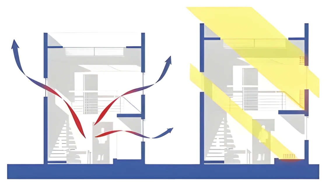
- Sunlight (radiant energy) entering through windows to heat interiors or store energy in thermal mass (direct solar gains)
- Sunlight warming up exterior building surfaces (“indirect solar gains”)
- Losing inside air to the outside, or vice-versa, through leaks and infiltration
- Air being intentionally introduced to the building to provide fresh air/ventilation or being exhausted from point sources.
Material choices, envelope design, and envelope sealing dramatically affect the amount of solar conducted and convected energy that enters and leaves the building envelope. The degree to which each of these impact the building’s loads and the occupant’s comfort also depend on the temperature and humidity differences between indoors and outdoors, which are all constantly changing by season and time of day.
Understanding where heat energy is gained and lost in your design is an important first step towards successful passive design strategies. When it’s hot and sunny, it can be very important to reduce loads from solar radiation by using properly designed shades and windows with low solar heat gain. On the other hand, in a cold climate or in the winter, it’s often desirable to capture this free solar energy in some way.
See more on climate considerations
See more on heat transfer and thermal properties
See more on infiltration and latent heat
See more on shading design

All lighting energy becomes heat eventually
Internal Thermal Loads
Internal thermal loads come from heat generated by people, lighting, and equipment. These are also sometimes called core loads or internal gains. Lighting and most equipment loads are sensible heat, while the metabolic heat generated by people bodies are a combination of sensible and latent loads. Some buildings or spaces are dominated by less common internal sources of sensible and latent internal loads such as large kitchens, swimming pools and locker rooms and health clubs or industrial processes.
The internal gains from lighting and equipment are generally equal to their energy use: when a light fixture converts a watt-hour of electricity into photons, those photons bounce around the room until they get absorbed, turning their light energy into heat energy.
Likewise, all the electrical energy that the lighting fixture did not turn into photons turns directly into heat energy, due to inefficiency.
The same is true of equipment: electrical energy used to move mechanical parts is transformed into heat via friction, energy used to power electronics turns into heat via electrical resistance, etc.
The thermal load of people depends on the number of people and their activity level. It can be as little as 70-80 watts for an adult sleeping to over 1,000 watts for an athlete engaging in intense exercise.

Thermal loads from people doing different activities
Internal vs. External Loads
Densely populated buildings with high activity and/or energy-intensive equipment (e.g. office buildings, movie theaters) are generally dominated by internal loads, while sparsely populated buildings with little activity or equipment (e.g. single family residences, warehouses) are generally dominated by external loads.
The building program and massing also help determine how important internal heat loads are compared to external loads from sun, wind, and ambient temperatures.
Heating and Cooling Loads
Internal and external thermal loads translate to heating and cooling loads. This is how much heat energy you need to heat and cool the building, and control moisture within the building.
Loads are usually calculated as the amount of energy that needs to be moved into or out of the building to keep the temperature at a specified point (setpoint).
- If heat gains are greater than envelope and ventilation losses, the building or space has a net cooling load (the building is too hot).
- If heat losses are greater than the internal gains, the building or space has a net heating load (the building is too cold).
- The heating thermostat setpoint is often different than the cooling thermostat setpoint both to save energy and because of human preference. The distribution of heating and cooling loads is climate dependent.
The heating and cooling loads below provide a break-down for what drives the heating and cooling energy demand.

Monthly heating and cooling load charts tell you where heat energy is being gained and lost.

An explanation for how to interpret heating and cooling load charts.

When interpreting energy load charts, pay attention to whether the biggest heat losses and gains come from internal or external loads.
Also note that it is the PEAK heating and cooling loads that are used by engineers to size HVAC equipment. These energy analysis graphs are meant to help understand energy flows, not size equipment. However, using energy analysis tools can allow you to better understand and calculate energy use so that you can avoid oversizing equipment and look past the typical “rules of thumb.”
Using Energy to Meet Heating and Cooling Loads
The values in the heating and cooling load charts above represent the amount of heating or cooling required, not the amount of energy a HVAC system would actually consume to generate the required load.
Passive systems reduce the energy demand or meet it naturally. Active systems move heat and moisture using gas or electricity. How much and what type of fuel the HVAC system will consume depends on the system type and efficiency.
When using active systems, it usually takes more energy to meet heating loads than it does to meet cooling loads. Heating systems based on combustion of a fuel are approximately 75%-95% efficient at converting the chemical energy in the fuel to heat delivered to the building. The efficiency of cooling systems (and heat pumps in heating mode) is not measured in percent efficiency because they do not convert potential energy to delivered heat, rather they use energy, most commonly electricity, to move heat either into or out of a building. The Whole Building Design Guide provides ranges of efficiency values and sizes that are typical for various types of cooling systems – see WBDG. Heat pumps and air conditioners use energy to move heat, they do not generate coolth – see Heat Pumps). The cooling effect that we feel is the removal of heat rather than the addition of coolth.
Also, when you put cost into the equation it brings another level of complexity because heating fuel is much cheaper per unit of energy than electricity. Building owners often spend more on energy to cool their building than to heat their building. There are many reasons for this, but the easiest to understand is that electricity typically costs three to five times more than heating fuel per unit of energy.
Balance Points
The concept of a building’s balance point can help designers determine when heating or cooling is required in the building. The balance point is the outdoor temperature at which the building makes a transition from a heating need to a cooling need. It is calculated by comparing internal heat gains (from people, equipment, etc) with external heat losses (from building infiltration, etc). It is not the ideal comfort temperature inside the building. It is the temperature at which the building’s heat gains equal its losses.
- If the temperature is BELOW the balance point, heating is required.
- If the temperature is ABOVE the balance point, cooling is required.
- If the temperature is AT the balance point, no heating or cooling is required, because the building is gaining as much heat as it is losing.
For example, if the balance point of a building is 65 degrees Fahrenheit and the outdoor temperature is 75 degrees Fahrenheit, a passive cooling strategy like shading would be helpful at that time.
Buildings that have high internal heat gains (like offices), and low rates of heat loss (well-sealed and well-insulated), will have a lower balance point.
Equipment and Lighting Loads
Lighting, HVAC equipment, water heaters, and appliances all consume energy in the form of either electricity or fuel. All of these things are important to understand and optimize for high performance building design, and are important inputs for whole building energy analysis simulation.
The equipment, lighting, and plug loads described below are determined by the building’s intended use, its occupancy, and its scheduling. In short: its program.
Lighting Loads
Lighting loads are the energy used to power electric lights; they make up nearly a third of US commercial building energy use, but for residential buildings they are generally only 10 – 15%. Lighting loads in a building are often referred to in terms of a “Lighting Power Density” that is measured in watts per square foot or square meter.
When deciding which lighting products to use, look at the efficiency (or luminous efficacy) of the products. More efficient light sources and fixtures not only reduce lighting loads, but also reduce cooling loads for the same visible brightness.
Plug loads
Plug loads are the electricity used for other equipment, like computers and appliances; they make up 20 – 30% of energy loads in US commercial buildings, and 15 – 20% of home energy, though these numbers are growing as electronics become more pervasive.
Plug loads are sometimes included in “Equipment Power Density” (EPD) and sometimes they are separated. When doing building analysis, it’s important to know which value you’re inputting.
| Equipment | Rated Power (watts) |
| Desktop computer | 120 |
| Notebook computer | 45 |
| 17” LCD Display | 75 |
| Desktop laser printer | 120 |
| Office laser printer | 250 |
| Office copier | 750 |
| Refrigerator | 750 |
| Dishwasher | 1,200 |
| Television | 100 |
| Commercial refrigerator | 1,000 |
| Commercial fryer | 10,000 |
| Clothes washer | 350 |
| Clothes dryer | 2,000 |
Plug loads for specific items
(Source: USGBC and EnergyStar)
Equipment Loads
Equipment, like HVAC systems and water heaters, is the other main internal load. This is typically separated from plug loads and is given in terms of an “Equipment Power Density,” which is measured in watts per square foot or square meter .
When deciding which equipment to use, look at third-party quantitative reviews, or read the maximum power use listed on product specification sheets (average power use data is usually not available because it can vary greatly by usage.)
Example Internal Loads for Different Space Types

Note that this information can vary greatly based on the design and use of the space. Use more precise and specific estimates when available. (Sources: United States Department of Energy (1 and 2), and Mechanical and Electrical Equipment for Buildings by Grondzik et al.)
Measuring Building Energy Use
Knowing how to measure energy use in buildings will help you set better energy efficiency goals. Energy Use Intensity (EUI) normalizes energy use by floor area and is useful for targets and benchmarks. But, when it comes to environmental impacts, you need to look upstream at “source energy.” Also, when it comes to energy efficiency measures, you need to know what end-uses take the most energy.
Energy Use Intensity
When comparing buildings, people not only talk about total energy demands, but also talk about “energy use intensity” (EUI). Energy intensiveness is simply energy demand per unit area of the building’s floorplan, usually in square meters or square feet. This allows you to compare the energy demand of buildings that are different sizes, so you can see which performs better.

Autodesk’s Insight energy analysis tool report building performance in terms of EUI and Annual Cost.
EUI is a particularly useful metric for setting energy use benchmarks and goals. The EUI usually varies quite a bit based on the building program, the climate, and the building size. The charts below, based on data from CBECS data from the United States, can give you an idea of the range of EUIs to expect based on these parameters.

Energy Use Intensities based on building activity (building program).
- Food service and health care buildings are the most energy intensive
- Warehouses, retail, and service buildings are less energy intensive.
- There’s a large spread between building types (the most energy intensive buildings use over 4 times as much energy as the least energy intensive non-vacant buildings.
Table available for download here. Data from the 2003 CBECS Survey Data for USA.

Energy Use Intensities based on building area.
- Large buildings are more energy intensive than small buildings, but small buildings can also be energy intensive
Table available for download here. Data from the 2003 CBECS Survey Data for USA.
Site Energy vs. Source Energy

The electricity that you use on your site, may use much more energy upstream.
1kWh of site electricity requires 3.3 kWh of source energy in the United States.
The energy intensity values in the tables above only consider the amount of electricity and fuel that are used on-site (“secondary” or “site” energy). They do not consider the fuel consumed to generate that heat or electricity. Many building codes and some tabulations of EUI attempt to capture the total impact of delivering energy to a building by defining the term “primary” or “source” energy which includes the fuel used to generate power on-site or at a power plant far away.

1 kWh of site electricity from a solar panel on the building’s roof is equal to 1 kWh of source energy, because the solar panel itself is the source.
When measuring energy used to provide thermal or visual comfort, site energy is the most useful measurement. But when measuring total energy usage to determine environmental impacts, the source energy is the more accurate measurement.
Sometimes low on-site energy use actually causes more energy use upstream. For example, 2 kWh of natural gas burned on-site for heat might seem worse than 1 kWh of electricity used on-site to provide the same heating with a heat pump. However, 1 kWh of site electricity from the average US electrical grid is equal to 3.3 kWh of source energy, because of inefficiencies in power plants that burn fuel for electricity, and because of small losses in transmission lines. So in fact the 2 kWh of natural gas burned on site is better for heating. The table below provides the conversion factors assumed by the US Environmental Protection Agency for converting between site and source energy.

A table from the US EPA’s EnergyStar Performance Ratings Methodology for Incorporating Source Energy Use.
Energy End Uses
Commercial and residential buildings use energy differently. Commercial buildings are usually dominated by internal loads dominated (more people, lights, and equipment), and use more lighting than residential buildings. Residential buildings are usually dominated by envelope loads, and a larger percentage of their energy use is used for heating and cooling to meet those loads.
Sankey diagrams of energy use are great visualizations to show where the energy comes from and goes in a building. In a Sankey diagram, the width of the bar represents the quantity being measured and the chart flows “upstream to downstream” (usually following arrows).
In the Sankey diagrams shown below from the USDOE, energy sources are shown on the left (coal, natural gas) and energy end-uses are shown on the right (space heating, lighting, appliances). You can clearly see the difference between site energy and source energy in this diagram by the arrow that trails off at the top due to electric power plant transmission and distribution losses. These losses are one of the main reasons that electricity is much more expensive per unit of energy than natural gas or fuel oil.

This Sankey diagram of residential building energy use in the United States shows that…
- Space heating dominates energy use and is primarily met by natural gas.
- Water heating is the second largest energy use, and is also met primarily by natural gas.
- Lighting is the largest user of electricity, and the third largest energy end-use.
- There are a lot of conversion and transmission losses from the coal that generates electricity. This make the total “source energy” significantly larger than the “site energy.”
- Renewable energy sources like wind, geothermal, PV (Photovoltaic) are dwarfed by coal and natural gas.

This Sankey diagram of commercial building energy use in the United States shows that…
- Space heating dominates energy use and is primarily met by natural gas.
- Lighting is the second largest energy use and is the largest user of electricity.
- Other/unallocated uses are very large as a percentage.
- There are a lot of conversion and transmission losses from the coal that generates electricity. This make the total “source energy” significantly larger than the “site energy.”
- Renewable energy sources like wind, geothermal, PV (Photovoltaic) are dwarfed by coal and natural gas.